Virtual Home Lab with Hyper-V (Part 2)
Part 2 of 3 - VLAN Configuration
This guide is part 2 of a 3 part series for setting up a virtualised home lab with Hyper-V.
In this part, we will be covering the following:
- Creating VLANs in pfsense
- Configuring DHCP Service for VLAN
- Allowing access from VLAN10 to webconfigurator
- Configuring Hyper-V for VLANs assignment
What is VLAN?
Virtual Local Area Network(VLAN) allow us to create logical networks on top of a physical one. This would allow only hosts within the same VLAN to talk to each other. For hosts to communicate cross VLAN, a router would be required. A layer 2 switch would not be able to route traffic between networks because routing is done at the network layer (Layer 3 of OSI model).
In our lab setup, the pfsense firewall acts as a router to route traffic between networks. This include the VLANs that we will be creating in this part. VMs connected to Lab Private would have the interface tagged with a VLAN ID and configured to be Access mode. This allow the switch to send frames to only interfaces that has the same VLAN ID tagging as the frame. For the interface between the pfsense firewall and Lab Private, it would be configured to allow frames with any VLAN ID to be sent by setting it as a Trunk mode.
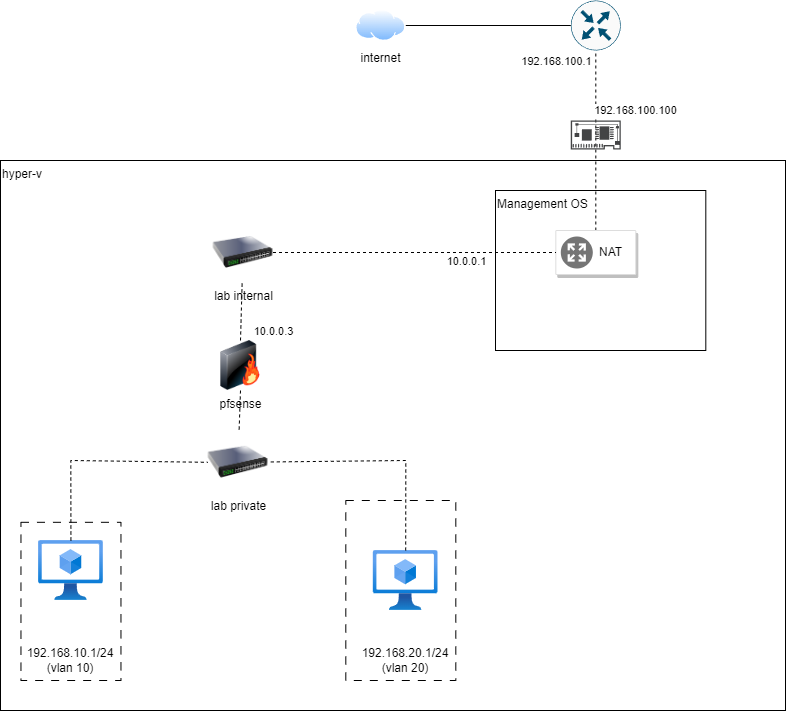
In our setup, 2 clients has been created to be separated into 2 different VLANs. Thus, we will set up 2 VLANs for this guide. However, you may choose to add more VLANs if needed.
Creating VLANs in pfsense
To create the VLANs at pfSense, we will use pfsense’s webconfigurator. Webconfigurator is the a Graphical User Inteface (GUI) to configure the pfsense firewall via web.
- Use any of the VM set up previously to access pfSense GUI web configurator via https://192.168.1.1.
- At the login page, use the following default credentials to log in:
admin:pfsense. - We can safely ignore the default password warning for now. But if you would like to change it now, do remember your password!
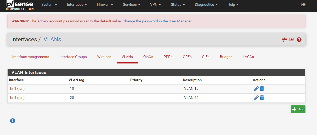
Go to Interfaces > Assignments. Select the VLANs tab and click Add. Use the settings below for creating 2 VLANs .
VLAN 10:
1
2
3
4
 Parent Interface: hn1
 VLAN Tag: 10
 VLAN Priority: 0
 Description: VLAN 10
VLAN 20:
1
2
3
4
 Parent Interface: hn1
 VLAN Tag: 20
 VLAN Priority: 0
 Description: VLAN 20
Once both VLANs are created, you will see something like below.
- Go back to the Interface Assignments tab. You would see that there is an option to add inteface assignments for available network ports.
- Click on Add twice to add both the VLANs as an interface. You will see something like below after adding both VLANs as an interface.
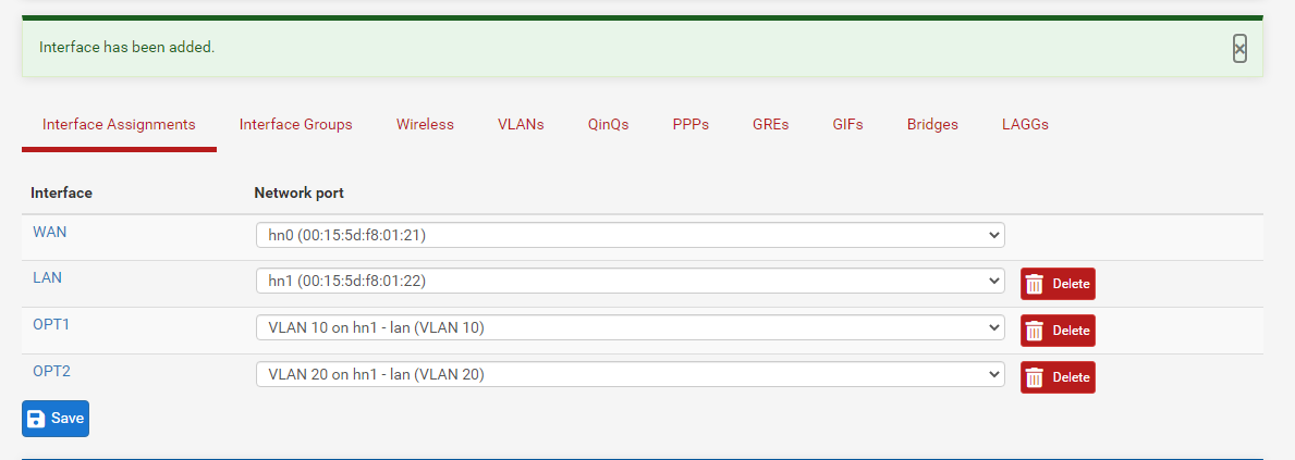
- Note that the OPT1 interface has been mapped to VLAN10 and OPT2 interface has been mapped to VLAN20.
Configuring DHCP Service for VLANs
Next, we will configure DHCP service to issue IP address for each VLAN. To do so, we will need to configure the VLAN interfaces and enable DHCP for each of them.
For each interface OPT1 and OPT2, follow the steps for both Configuring Interface and Enabling DHCP Service . I will use OPT1 and VLAN10 as an example.
Configuring Interface
- Go to Interfaces > OPT1
- Under General Configuration,
- Checked Enable Interface
- Set IPv4 Configuration Type to Static IPv4
- Set IPv6 Configuration Type to None
- Under Static IPv4 Configuration,
- Set IPv4 Address to
192.168.10.1for OPT1,192.168.20.1for OPT2 - At the right, set the value (subnet mask) to
/24
- Set IPv4 Address to
- Click Save
- Click on Apply Changes. Repeat steps 1-4 for OPT2 before proceeding to the next section.
Enabling DHCP Service
- Go to Services > DHCP Service.
- Click on OPT1 Tab
- Under General DHCP Options
- Checked Enable DHCP Server on OPT1 Interface
- Under Primary Address Pool
- Set Address Pool Range
- From:
192.168.10.100(OPT1)192.168.20.100(OPT2) - To:
192.168.10.150(OPT1)192.168.20.150(OPT2)
- From:
- Set Address Pool Range
- Scroll down and click
Save. - Click
Apply Changes.
You can select a different IP range but do take note that the first address
192.168.x.1was used as the default interface IP address.
Allowing access from VLAN10 to webconfigurator
This section is not related for configuration of VLANs. But for convenience, we would also need to allow VLAN10 to be able to access the firewall for configuration. This is to prevent VMs from getting locked out once we switch our VM’s traffic to use VLAN access.
- Go to
Firewall > Rules. Click on OPT1 tab. - Click on any of the Add button to add a firewall rule. The setting for the rule is as follows:
1
2
3
4
5
 Action: Pass
 Interface: OPT1
 Source: OPT1 Subnets/OPT1 Net
 Destination: OPT1 address
 Destination Port Range: Choose "HTTPS (443)" in "From" dropdown.
- Click the
Savebutton at the bottom and apply the changes.
Configuring Hyper-V for VLANs assignment
VLAN is achieved by having a tag to each ethernet frame. Extracted from Wikipedia below, we can see that there is a 802.1Q tag with 4 octets for an optional VLAN tag. Thus, we will configure the interface of the VM to tag ethernet frames with the correct VLAN ID. We would also set the interface mode to be either Access or Trunk mode. 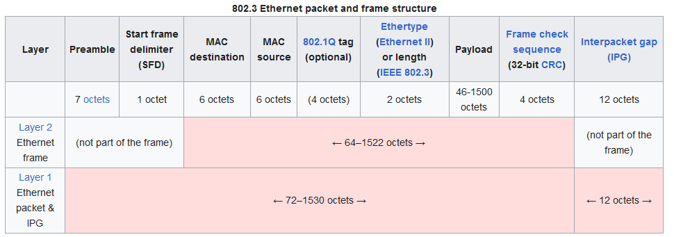
Configuring Windows 10 Client VM settings for VLAN
Start powershell as an administrator on the management host for the next few steps.
Get our VM names with the following command. Note the names of the windows client. (If you follow the previous guide, it will be Windows 10 (vlan10) and Windows 10 (vlan20))
1
Get-VM
For each of the windows 10 client, we will need to configure the virtual network adapter to be Access mode and the respective VLAN ID.
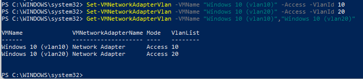
- Configuring VLAN access mode and VLAN ID for
Windows 10 (vlan10)1
Set-VMNetworkAdapterVlan -VMName "Windows 10 (vlan10)" -Access -VlanId 10
- Configuring VLAN access mode and VLAN ID for
Windows 10 (vlan20)1
Set-VMNetworkAdapterVlan -VMName "Windows 10 (vlan20)" -Access -VlanId 20
Confirm both has been set correctly with the following command.
1
 Get-VMNetworkAdapterVlan -VMName "Windows 10 (vlan10)","Windows 10 (vlan20)"
Configuring pfsense VM settings for VLAN
Next, we need to set the LAN interface of the firewall to be Trunk mode. A Trunk interface allows multiple VLAN traffic to pass through.
- Get get the network adapters of our firewall with the follow command.
1
 Get-VMNetworkAdapter -VMName "Firewall"
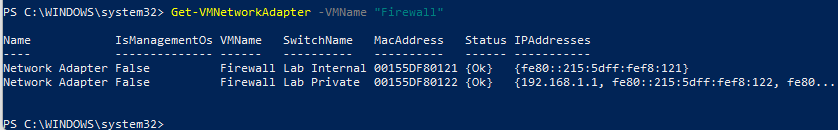
- Take note of the MAC Address of network adapter connected to
Lab Private. For mine, it would be00155DF80122 - Run the following command after replacing the MAC Address extracted previously.
1
Get-VMNetworkAdapter -VMName "Firewall" | Where-Object {$_.MacAddress -eq "<MacAddress>"} | Set-VMNetworkAdapterVlan -Trunk -AllowedVlanIdList "10,20" -NativeVlanId 1 - Then run the following command to ensure that it has been set.
1
 Get-VMNetworkAdapter -VMName "Firewall" | Where-Object {$_.MacAddress -eq "<MacAddress>"} | Get-VMNetworkAdapterVlan
Testing
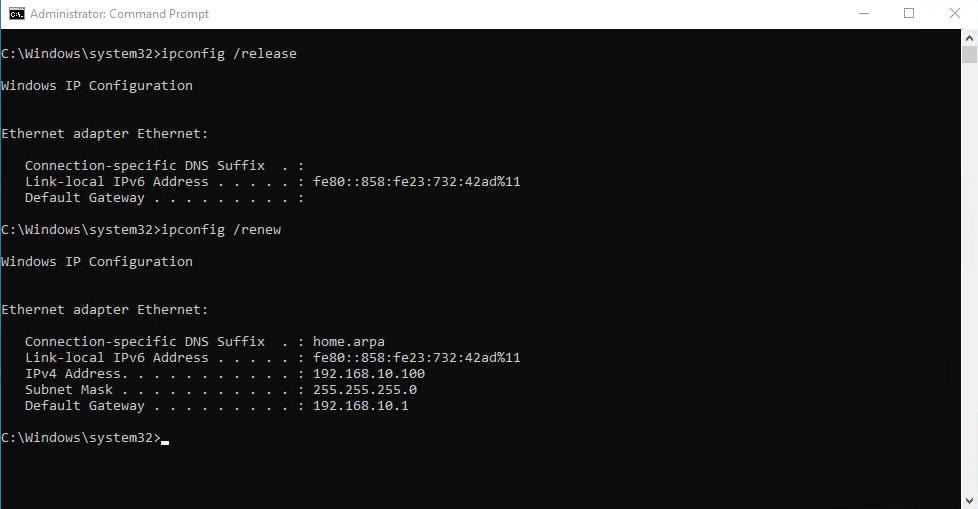
Let us test if the VLANs and the DHCP service is working. Go to each VM and start command prompt as administrator.
- Run the following command to get a new IP.
1
2
 ipconfig /release
 ipconfig /renew
Verify that the IP assigned is correct for the respective VLAN. 192.168.10.x for VLAN 10 and 192.168.20.x for VLAN 20.
windows 10 (vlan10)
windows 10 (vlan20)
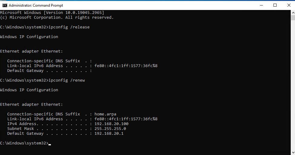
Note: If the Default Gateway is not set, go back to the DHCP server for each VLAN interface via Services > DHCP Server and set the Gateway under Other DHCP Options as the IP of the interface e.g
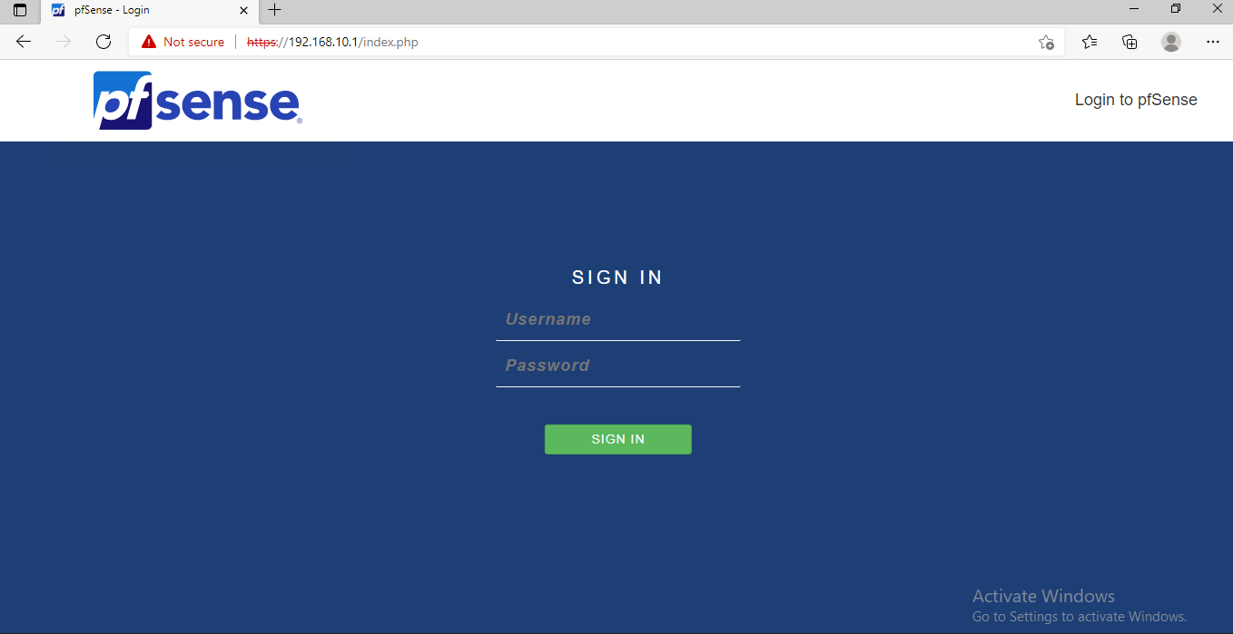
192.168.10.1for OPT1 and192.168.20.1for OPT2. This settings tell the DHCP clients that any destination address not within the local network should be routed to the default gateway.- Next go to the client Windows 10 (vlan10), we will try to access the web configurator from here. Go to https://192.168.10.1. You will be able to see the login page.
If we try to access the web configurator from the client Windows 10 (vlan20), we would not able to access the web configurator as there are no firewall rules that allows it.
Now that we have configured both our VLANs. In the last part, we will configure our pfsense firewall such that clients in VLAN 10 are able to access the internet, but not for the clients in VLAN20.
See you in the next part!